

Overview
Electric current is the rate of flow of electric charge, measured in amperes and governed in metal wires by Ohm's law. Current heats a resistance, makes a magnetic field and, in reverse, is induced by a changing magnetic field; these effects run fuses, motors, generators and transformers, while semiconductors and superconductors extend them into chips, LEDs, solar cells and powerful magnets.
Electric Current, Potential Difference and Resistance
What Is Electricity? Electric Charge, Electric Current and Its Unit
Electricity is a controllable and convenient form of energy used in homes, schools, hospitals and industries. When electric charge flows through a conductor such as a metal wire, there is an electric current in it, and a continuous, closed path for that current is an electric circuit. Break the circuit anywhere, as a switch does, and the current stops.
Current was first thought of as a flow of positive charge, before electrons were known, so by convention its direction is taken as opposite to the flow of electrons. One coulomb is the charge of nearly 6 × 10 to the power 18 electrons, each carrying 1.6 × 10 to the power minus 19 coulomb. An ammeter measures current and is always connected in series.
Charges flow only when there is a difference of electric pressure, the potential difference, which a cell or battery produces by chemical action. The potential difference between two points is the work done to move a unit charge from one to the other, measured in volts: one volt is one joule per coulomb. A voltmeter measures it and is connected in parallel.
Ohm's Law, Resistance and Resistivity
In 1827 the German physicist Georg Simon Ohm found that the current through a metallic wire is directly proportional to the potential difference across its ends, provided its temperature stays the same. This is Ohm's law: V equals I × R, where R, the resistance, is the property of a conductor that resists the flow of charge. It is measured in ohms, and if the resistance is doubled the current is halved.
The resistance of a uniform conductor is directly proportional to its length and inversely proportional to its area of cross-section, and it depends on the material. The constant of proportionality is the resistivity, a property of the material measured in ohm metre. Metals and alloys have resistivities of 10 to the power minus 8 to 10 to the power minus 6 ohm metre; insulators such as rubber and glass, 10 to the power 12 to 10 to the power 17.
- Alloys for heating: An alloy has a higher resistivity than its constituent metals and does not oxidise readily when hot, so nichrome is used in electric irons and toasters.
- Filaments: Tungsten, with a melting point of 3380 degrees Celsius, is used for bulb filaments.
- Transmission lines: Copper and aluminium, with very low resistivity.
- Temperature: Both resistance and resistivity vary with temperature.
Resistors in Series and Parallel
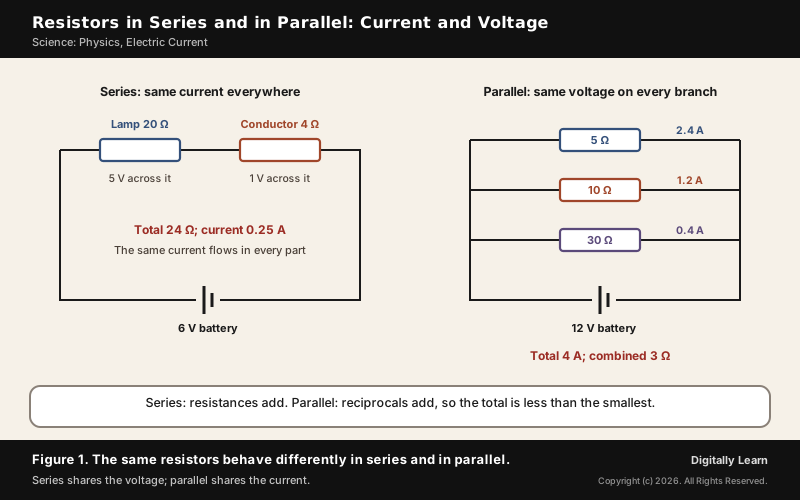
In a series circuit the resistors are joined end to end, the same current flows through each, and the total potential difference is the sum of the potential differences across them. The resistances simply add, so the combination has more resistance than any single resistor. A 20 ohm lamp and a 4 ohm conductor on a 6 volt battery make 24 ohm and draw 0.25 ampere.
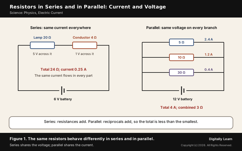
In a parallel circuit each resistor gets the full potential difference, and the total current is the sum of the currents in the branches. The reciprocal of the combined resistance is the sum of the reciprocals, so the total is less than the smallest resistance: 5, 10 and 30 ohm in parallel on 12 volts carry 2.4, 1.2 and 0.4 ampere, 4 ampere in all, and act as 3 ohm.
Heating Effect of Electric Current and Electric Power
Joule's Law of Heating and the Electric Fuse
When the circuit is purely resistive, all the energy the source supplies is dissipated as heat; this is the heating effect of electric current. The heat produced in time t is H equals I squared × R × t, Joule's law of heating: it is proportional to the square of the current, to the resistance and to the time. Electric irons, toasters, ovens, kettles and heaters all use it. The resistance itself comes from the drifting electrons colliding with the heavy fixed ions of the metal, not from metal atoms colliding with one another.
A bulb uses the same heating to make light: its tungsten filament must get very hot without melting, and the bulb is filled with chemically inactive nitrogen and argon to prolong the filament's life. Even so, most of the power appears as heat and only a small part as light. The heat and the laws governing it are explained in Part 2: heat and thermodynamics.
An electric fuse protects circuits and appliances. It is a piece of wire of a metal or alloy of suitable melting point, such as aluminium, copper, iron or lead, placed in series with the device. If the current exceeds the rated value, the fuse wire heats up, melts and breaks the circuit; domestic fuses are rated 1, 2, 3, 5 and 10 ampere, and an iron of 1 kilowatt on 220 volts draws 4.54 ampere and needs a 5 ampere fuse.
Electric Power, Kilowatt-hour and Domestic Electric Circuits
Electric power is the rate at which electrical energy is consumed: P equals V × I, which is also I squared × R and V squared divided by R. Its unit is the watt, the power of a device carrying 1 ampere at 1 volt. The commercial unit of electrical energy is the kilowatt hour, the familiar unit on a bill, equal to 3.6 × 10 to the power 6 joules; a 400 watt refrigerator running 8 hours a day uses 96 units in 30 days.
Homes receive alternating current at 220 volts and 50 hertz through a live wire with red insulation and a neutral wire with black insulation, via a main fuse and an electricity meter. A third, green earth wire is connected to a metal plate deep in the ground; appliances with a metal body are joined to it so that any leakage of current keeps the body at earth's potential and the user does not get a severe shock.
- Two circuits: A 15 ampere circuit for geysers and air coolers, and a 5 ampere circuit for bulbs and fans.
- Short circuit: When the live and neutral wires touch, through damaged insulation or a faulty appliance, the current rises abruptly.
- Overloading: Also caused by a sudden rise in supply voltage or too many appliances on one socket; the fuse stops the unduly high current.
Electricity is not used up as electrons: what a household pays for is the energy used to move electrons through its appliances. How much energy the whole country draws at its busiest hour is tracked as India's peak power demand.
Magnetic Effects of Electric Current
Magnetic Field Lines and the Earth's Magnetic Field
In 1820 Hans Christian Oersted found that a compass needle is deflected when an electric current passes through a nearby wire, showing that electricity and magnetism are linked. The region around a magnet in which its force can be detected is its magnetic field, drawn as field lines: they leave the north pole, enter the south pole, are closed curves, crowd together where the field is strong, and never cross one another.
The Earth itself behaves like a magnet, with a field of the order of 10 to the power minus 5 tesla. It is thought to arise from electric currents in the molten iron and nickel of the outer core, the dynamo effect. The axis of this field is tilted by about 11.3 degrees to the axis of rotation, and the north magnetic pole lies in northern Canada; confusingly, it behaves like the south pole of a bar magnet, since the field lines go in there.
- A wandering pole: James Clark Ross found the North Magnetic Pole in northern Canada in 1831, and it has since moved across the Canadian Arctic towards Russia, at about 45 kilometres a year at present.
- Reversals: The field has reversed at least 183 times in the last 83 million years; the latest reversal was 780,000 years ago.
- Thumba: The Thumba Equatorial Rocket Launch Station near Thiruvananthapuram was set up in 1962 because of its closeness to the geomagnetic equator, and India’s first sounding rocket flew from it on 21 November 1963.
Right-Hand Thumb Rule, Solenoid and Electromagnet
A straight wire carrying a current is surrounded by field lines in concentric circles. The field grows stronger as the current increases and weaker farther from the wire. Its direction follows the right-hand thumb rule: hold the wire in the right hand with the thumb along the current, and the fingers curl in the direction of the field.
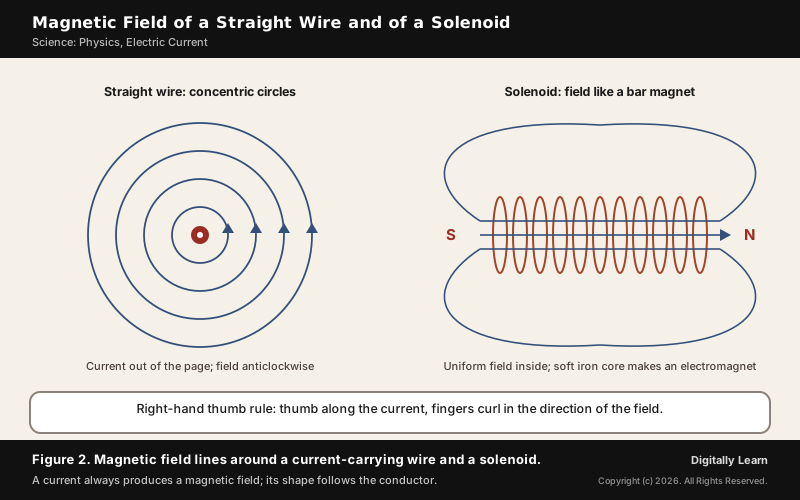
Bending the wire into a loop makes the field inside point one way, and a coil of n turns gives n times the field of one turn. A solenoid, a coil of many closely wound turns of insulated copper wire, has a field like a bar magnet's, with a north and a south end, and the field inside it is uniform. A soft iron core placed inside is magnetised strongly, making an electromagnet.
Force on a Conductor: Fleming's Left-Hand Rule and the Electric Motor
A magnet exerts a force on a current-carrying conductor placed in its field, as Andre Marie Ampere suggested. The force is largest when the current is at right angles to the field, and it reverses when either the current or the field is reversed. By Fleming's left-hand rule, with the thumb, forefinger and middle finger of the left hand at right angles, the forefinger along the field and the middle finger along the current, the thumb gives the force.
An electric motor turns this force into rotation, converting electrical energy into mechanical energy. A coil sits between the poles of a magnet; the forces on its two sides act in opposite directions and turn it. A split ring, the commutator, reverses the current every half turn, so the coil keeps turning the same way.
- Commercial motors: Use an electromagnet, many turns of wire and a soft iron core, together called the armature.
- Uses: Fans, refrigerators, mixers, washing machines and computers.
- Moving charges: The magnetic force acts on a moving charge, and on a negative charge it acts opposite to that on a positive one.
Electromagnetic Induction, Alternating Current and Transformers
Faraday's Law, Lenz's Law and Fleming's Right-Hand Rule
Push a magnet towards a coil joined to a galvanometer and the needle deflects; pull it away and the needle deflects the other way; hold it still and there is no current. Switching a current on or off in one coil likewise induces a momentary current in a second coil nearby. The cause in every case is a change in the magnetic field lines linked with the coil.
The direction of the induced current follows Lenz's law, stated in 1834: it tends to oppose the change in magnetic flux that produced it. For a conductor moving through a field, Fleming's right-hand rule gives the direction: with the forefinger along the field and the thumb along the motion, the middle finger points along the induced current.
Electric Generator and the Difference Between AC and DC
An electric generator uses mechanical energy to rotate a coil in a magnetic field, and electromagnetic induction sets up a current in it. Every half rotation the two sides of the coil swap between moving up and moving down, so the current reverses. A current that changes direction at equal intervals is alternating current; fitting a split-ring commutator instead of slip rings gives direct current.
| Point | DC | AC |
|---|---|---|
| Direction | Always one way | Reverses periodically |
| Sources | Cells and batteries | Most power stations |
| Generator | Split-ring commutator | Slip rings |
| Transformer | Cannot be used | Steps voltage up or down |
| In India | Batteries, solar cells | 50 hertz, 220 volts at home |
In India, alternating current changes direction every 1/100 second, a frequency of 50 hertz. Its great advantage is that it can be transmitted over long distances without much loss of energy, which is why most power stations produce it and why the electric generator in a power plant is an AC machine.
Transformer and Long-Distance Power Transmission
A transformer changes an alternating voltage to a higher or lower value by mutual induction. Two coils, insulated from each other, are wound on a soft iron core; an alternating current in the primary coil makes an alternating flux that induces a voltage in the secondary. The ratio of the voltages equals the ratio of the numbers of turns, and since a transformer passes on the power, the current changes the other way.
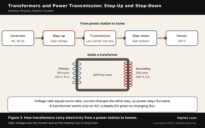
- Step-up: More turns in the secondary; a primary of 100 turns and a secondary of 200 turns turn 220 volts at 10 ampere into 440 volts at 5 ampere.
- Step-down: Fewer turns in the secondary; the voltage falls and the current rises.
- Losses: Flux leakage, heating in the windings and eddy currents in the core, though a well designed transformer is more than 95 per cent efficient.
The generator's output is stepped up for transmission, which lowers the current and so cuts the I squared R heating loss in long lines. It is stepped down again at sub-stations near consumers, and further at distribution sub-stations and poles, before it reaches homes.
Semiconductors, Superconductors and the India Semiconductor Mission
Conductors, Semiconductors and Insulators: Doping and the P-N Junction Diode
Solids are grouped by resistivity. Metals have very low resistivity, of 10 to the power minus 2 to 10 to the power minus 8 ohm metre; insulators very high, 10 to the power 11 to 10 to the power 19; and a semiconductor lies in between, at 10 to the power minus 5 to 10 to the power 6. Silicon and germanium are elemental semiconductors, and gallium arsenide and cadmium sulphide are compound ones.
A pure, intrinsic semiconductor conducts poorly at room temperature. Adding a few parts per million of a suitable impurity, doping, raises its conductivity many times: a pentavalent dopant such as arsenic or phosphorus makes it n-type, with extra electrons, and a trivalent dopant such as boron or aluminium makes it p-type, with holes that act as positive charges.
A p-n junction, formed where a p-region meets an n-region in one crystal, is the basic building block of diodes and transistors. A diode conducts when forward biased and not when reverse biased, so a p-n junction diode can rectify alternating current: a half-wave rectifier passes only half of each cycle, and a full-wave rectifier uses two diodes to use both halves.
LED Lamps, Solar Cells and Photodiodes
Some p-n junctions deal in light. A light emitting diode converts electrical energy into light, a photodiode detects light, and a solar cell converts sunlight into electricity. In a solar cell light creates electron-hole pairs near the junction, the junction's field separates them, and the p-side becomes positive and the n-side negative, giving a photovoltage without any external bias.
- LED lamps: Significantly more energy-efficient than incandescent and fluorescent lamps, and several times longer lasting.
- Fluorescent lamps and CFLs: Make ultraviolet light in mercury vapour, which a phosphor coating turns into visible light; the mercury complicates their disposal.
- Photodiode: Operated under reverse bias; the current rises with the intensity of light, so it is used to detect optical signals.
How LEDs fit into light and optics more broadly is covered in Part 4: reflection and refraction of light.
Superconductors and Their Uses
A superconductor is a material whose electrical resistance is exactly zero below a characteristic critical temperature. An ordinary metal's resistance falls gradually as it is cooled; a superconductor's drops abruptly to zero, and a current started in a loop of superconducting wire can keep flowing indefinitely with no power source.
Superconductivity was discovered in 1911 by the Dutch physicist Heike Kamerlingh Onnes. It is marked by the Meissner effect, the complete expulsion of the magnetic field from the interior of the material as it becomes superconducting. Niobium-titanium, easy to shape into wire, became the workhorse material for superconducting magnets in MRI scanners and in the bending and focusing magnets of particle accelerators.
India Semiconductor Mission: Fabs, Packaging and Chip Design
Semiconductor chips are the foundation of modern electronics, from phones and cars to satellites and defence systems. The Union Cabinet approved the programme for a semiconductor and display ecosystem in December 2021, run as the India Semiconductor Mission with an outlay of ₹76,000 crore. India consumes nearly 20 per cent of the world's microprocessor output, and the Mission aims to cut its dependence on imported chips.
- Semiconductor and display fabs: Fiscal support of 50 per cent of project cost on a pari-passu basis.
- Compound semiconductors, sensors and packaging: Support for assembly, testing, marking and packaging (ATMP and OSAT) units, first 30 per cent and now 50 per cent of capital expenditure.
- Chip design: The Design Linked Incentive scheme pays up to 50 per cent of eligible expenditure and 6 to 4 per cent of net sales for five years.
- Semi-Conductor Laboratory, Mohali: To be modernised.
By August 2025, 10 projects with a combined investment of about ₹1.60 lakh crore had been approved in 6 states, among them Micron's packaging unit at Sanand, Tata Electronics' fab with Taiwan's PSMC at Dholera and Tata's assembly and test unit at Morigaon in Assam. The Union Budget 2026-27 announced ISM 2.0, focused on equipment, materials and Indian chip intellectual property; the full list of units is tracked in India's Semiconductor Mission: fabs and ISM 2.0.
Previous Year UPSC-CSE Questions
Previous Year UPSC-CSE Questions By the end you will be able to draft model answers for the following UPSC questions. Each question carries a collapsible framework showing how to approach it in the exam.
- UPSC Mains 2025 GS-IIIIndia aims to become a semiconductor manufacturing hub. What are the challenges faced by the semiconductor industry in India? Mention the salient features of the India Semiconductor Mission.
How to structure the answer in the exam
Introduction: Introduce semiconductors as the foundation of modern electronics and India's aim, under the India Semiconductor Mission (December 2021, ₹76,000 crore), to become a manufacturing hub.
Body (sub-themes to develop):
- Challenges: capital-intensive, high-risk, long gestation and payback, rapid technology change.
- Inputs: semiconductor-grade water, high-quality power, logistics, research ecosystem.
- Skilled manpower and dependence on imported chips; fragile, concentrated global supply chains.
- Features: 50 per cent support for fabs and display fabs; support for ATMP/OSAT and compound semiconductors; Design Linked Incentive; SCL Mohali.
- Progress: 10 projects, about ₹1.60 lakh crore, 6 states; Dholera fab; ISM 2.0 on equipment, materials and IP; talent schemes such as Chips to Startup.
Conclusion: Conclude that sustained support, skills and a secure supply chain will decide whether India moves from packaging to advanced fabrication.
- UPSC Prelims 1998 Prelims-GSA fuse is used in main electric supply as a safety device. Which one of the following statements about the fuse is correct?
How to approach this Prelims question
Approach: Step 1: a fuse must stop an unduly high current, so it must sit in the path of that current, in series. Step 2: it stops the current by melting when the current exceeds its rating, so the property that matters is a suitable, low melting point. Step 3: test each option against these two facts; only (c) survives.
Trap to watch: A fuse in parallel would not break the circuit at all.
Key facts to recall:
- (a) Connected in parallel with the main switch: wrong. A fuse is placed in series with the device it protects; in parallel it could not break the circuit.
- (b) Made mainly from silver alloys: wrong. Fuse wire is a metal or alloy of suitable melting point, such as aluminium, copper, iron or lead.
- (c) Must have a low melting point: right. The fuse wire heats up and melts when the current exceeds its rating, breaking the circuit.
- (d) Must have a very high resistance: wrong. A large resistance in series would cut the current the appliance needs, since current equals voltage divided by resistance; the fuse only has to melt at the rated current.
Answer signal: Low melting point: option (c), the official answer, because a fuse works by melting.
- UPSC Prelims 1998 Prelims-GSAssertion and Reason:
- Assertion (A): The temperature of a metal wire rises when an electric current is passed through it.
- Reason (R): Collision of metal atoms with each other releases heat energy.
How to approach this Prelims question
Approach: Step 1: test the assertion. A current through a resistive wire dissipates energy as heat (H equals I squared R t), so its temperature rises: A is true. Step 2: test the reason. The heating comes from the drifting electrons colliding with the heavy fixed ions of the metal, not from metal atoms colliding with each other: R is false. Step 3: A true and R false is option (c).
Trap to watch: Resistance comes from electrons being hindered as they move, not from atoms colliding.
Key facts to recall:
- (a) Both true, R explains A: wrong. R is false.
- (b) Both true, R does not explain A: wrong. R is false, so this cannot hold.
- (c) A true, R false: right. The wire heats by Joule heating; the collisions are of electrons with fixed ions, not atoms with atoms.
- (d) A false, R true: wrong. A is true: a current does raise a wire's temperature, and R is the false half.
Answer signal: A true, R false: option (c), the official answer, because the heating comes from electron-ion collisions.
- UPSC Prelims 1996 Prelims-GSAssertion and Reason:
- Assertion (A): Transformer is useful for stepping up or stepping down voltages.
- Reason (R): Transformer is a device used in D.C. circuits.
In the context of the above two statements, which one of the following is correct?
How to approach this Prelims question
Approach: Step 1: a transformer changes an alternating voltage to a higher or lower value, so A is true. Step 2: it works by mutual induction, which needs a changing magnetic flux; a steady direct current gives no changing flux and so no induced voltage, so a transformer is not a DC device and R is false. Step 3: A true and R false is option (c).
Trap to watch: Steady direct current gives no changing flux and so no induced voltage.
Key facts to recall:
- (a) Both true, R explains A: wrong. R is false.
- (b) Both true, R does not explain A: wrong. R is false, so this cannot hold.
- (c) A true, R false: right. A transformer steps voltage up or down, but only on AC.
- (d) A false, R true: wrong. A is true, and R is the false half.
Answer signal: A true, R false: option (c), the official answer, because a transformer needs a changing flux.
- UPSC Prelims 2001 Prelims-GSTwo wires have their lengths, diameters and resistivities, all in the ratio of 1 : 2. If the resistance of the thinner wire is 10 ohms, the resistance of the thicker wire is
How to approach this Prelims question
Approach: Step 1: resistance equals resistivity × length divided by area, and area is proportional to the diameter squared. Step 2: the thinner wire has resistivity, length and diameter all equal to 1 unit, and its resistance is 10 ohms. Step 3: the thicker wire has resistivity 2, length 2 and diameter 2, so its area is 2 × 2 = 4 times larger. Step 4: its resistance is 10 × 2 × 2 divided by 4, which is 10 ohms.
Trap to watch: Doubling the diameter multiplies the area by four, not two.
Key facts to recall:
- (a) 10 ohms: right. 10 × 2 (resistivity) × 2 (length) divided by 4 (area) equals 10.
- (b) 5 ohms: wrong. This would follow only if the area doubled and nothing else changed.
- (c) 20 ohms: wrong. It takes the area as doubling instead of quadrupling (10 × 2 × 2 divided by 2).
- (d) 40 ohms: wrong. It ignores the larger area altogether (10 × 2 × 2).
Answer signal: 10 ohms: option (a), the official answer, because the fourfold area cancels the doubled resistivity and length.
- UPSC Prelims 2005 Prelims-GSConsider the following statements :
- The axis of the earth’s magnetic field is inclined at 23 ½° to the geographic axis of the earth.
- The earth’s magnetic pole in the northern hemisphere is located on a peninsula in northern Canada.
- Earth’s magnetic equator passes through Thumba in South India.
Which of the statements given above is/are correct?
How to approach this Prelims question
Approach: Step 1: statement 1 gives 23.5 degrees, which is the Earth's axial tilt; the magnetic axis is tilted about 11.3 degrees, so statement 1 is incorrect. Step 2: the north magnetic pole lies in northern Canada, so statement 2 is correct. Step 3: Thumba was chosen for its closeness to the geomagnetic equator, so statement 3 is correct. Step 4: 2 and 3 are correct, which is option (b).
Trap to watch: Mixing up the axial tilt (23.5 degrees) with the magnetic tilt (about 11 degrees).
Key facts to recall:
- (a) 1, 2 and 3: wrong. Statement 1 is incorrect; the magnetic axis is tilted about 11.3 degrees.
- (b) 2 and 3: right. The north magnetic pole is in northern Canada and the magnetic equator passes close to Thumba.
- (c) 2 only: wrong. It leaves out statement 3, which is correct.
- (d) 3 only: wrong. It leaves out statement 2, which is correct.
Answer signal: 2 and 3: option (b), the official answer, because the magnetic tilt is about 11 degrees, not 23.5.
- UPSC Prelims 2011 Prelims-GSWhat is the difference between a CFL and an LED lamp?
- To produce light, a CFL uses mercury vapour and phosphor while an LED lamp uses semi-conductor material.
- The average life span of a CFL is much longer than that of an LED lamp.
- A CFL is less energy-efficient as compared to an LED lamp.
Which of the statements given above is/are correct?
How to approach this Prelims question
Approach: Step 1: a CFL makes ultraviolet light in mercury vapour that a phosphor turns into visible light, while an LED is a semiconductor device, so statement 1 is correct. Step 2: LED lamps last several times longer than fluorescent lamps, so statement 2 is incorrect. Step 3: LED lamps are significantly more energy-efficient, so a CFL is the less efficient and statement 3 is correct. Step 4: 1 and 3 only, which is option (c).
Trap to watch: Statement 2 reverses the truth: the LED lasts longer.
Key facts to recall:
- (a) 1 only: wrong. Statement 3 is also correct.
- (b) 2 and 3 only: wrong. Statement 2 is incorrect; the LED lasts longer.
- (c) 1 and 3 only: right. The lighting method in 1 and the efficiency in 3 are both correct.
- (d) 1, 2 and 3: wrong. Statement 2 is incorrect.
Answer signal: 1 and 3 only: option (c), the official answer, because the LED, not the CFL, lasts longer.
Sources
- NCERT: Science (Class X), Electricity
- NCERT: Science (Class X), Magnetic Effects of Electric Current
- NCERT: Physics Parts I and II (Class XII): Magnetism and Matter; Electromagnetic Induction; Alternating Current; Semiconductor Electronics
- PIB: Cabinet approves programme for semiconductor and display ecosystem (15 December 2021)
- PIB: Fiscal support, MoUs and talent for chip manufacturing (2 April 2025)
- PIB: India's Semiconductor Revolution (3 August 2025)
- PIB: India Semiconductor Mission 2.0 (7 February 2026)
- NOAA NCEI: Tracking Changes in Earth's Magnetic Poles
- Vikram Sarabhai Space Centre: Genesis
- Wikipedia: Superconductivity
- Wikipedia: LED lamp
- Wikipedia: Compact fluorescent lamp
- Wikipedia: Geomagnetic reversal
- UPSC: Civil Services Examination question papers
Editorial Disclaimer
This article draws on the NCERT textbooks and the other sources listed on this page.


