
Overview
Previous Year Questions By the end of this article you will be able to draft model answers for the following UPSC questions. Each question carries a collapsible framework showing how to approach it in the exam.
- UPSC Prelims 2023 GS-I: Consider the following statements:
- In a seismograph, P waves are recorded earlier than S waves.
- In P waves, the individual particles vibrate to and fro in the direction of wave propagation whereas in S waves, the particles vibrate up and down at right angles to the direction of wave propagation.
Which of the statements given above is/are correct?
How to approach this Prelims question
Approach: Validate each statement against the standard physics of body waves; both must be correct for option (c).
Trap to watch: Reversing the particle-motion direction. P-waves are compressional (longitudinal): particles oscillate along the propagation direction. S-waves are shear (transverse): particles oscillate perpendicular to propagation.
Key facts to recall:
- P-waves travel faster than S-waves; they arrive first on a seismograph.
- P-waves are compressional and travel through solids, liquids, and gases.
- S-waves are transverse shear waves and travel only through solids.
Answer signal: Statement 1 true (P recorded before S). Statement 2 true (correct description of P versus S particle motion). Answer (c) Both 1 and 2.
- UPSC Prelims 2006 GS-I: Consider the following statements:
- The Richter scale is a logarithmic scale and so an increase of 1 magnitude unit represents a factor of 10 times in amplitude.
- Each integer reading of the Richter scale has an energy 100 times that of the previous integer reading.
Which of the statements given above is/are correct?
How to approach this Prelims question
Approach: Distinguish amplitude factor (10 per unit) from energy factor (approximately 31.6 per unit, NOT 100).
Trap to watch: Confusing amplitude scaling and energy scaling. Both are logarithmic but with different bases: amplitude scales as 10 per unit; energy scales as 10 to the power 1.5, which is approximately 31.6 per unit, not 100.
Key facts to recall:
- Richter scale is base-10 logarithmic for amplitude.
- Energy released scales as the 1.5 power of the amplitude: each unit of magnitude corresponds to roughly 31.6 times the energy, not 100 times.
- The 100-times-energy claim is a standard UPSC trap.
Answer signal: Statement 1 true (10 times in amplitude). Statement 2 false (energy is approximately 32 times, not 100). Answer (a) 1 only.
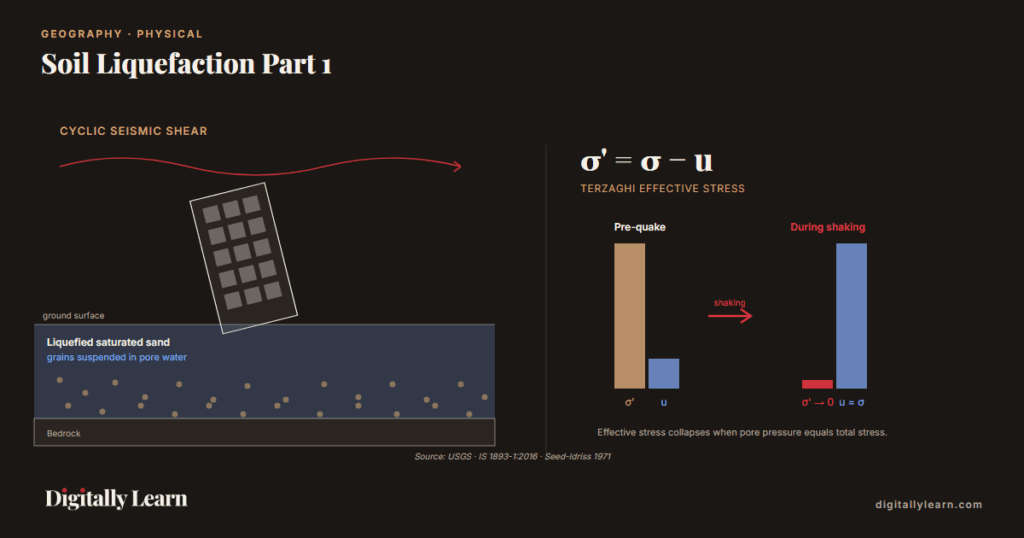
Soil liquefaction is the phenomenon in which saturated, loose, granular soils, principally fine sands, silty sands, and young alluvium, lose nearly all of their shear strength and bearing capacity during strong earthquake shaking. Repeated cyclic stress from seismic waves compresses water-filled pore spaces, pore-water pressure rises faster than it can drain through the soil mass, and the effective stress between soil grains drops toward zero. The soil ceases to behave as a solid and behaves like a heavy viscous fluid. Liquefaction is classified as a secondary earthquake hazard, distinct from ground shaking, but is often the most damaging effect in urban areas built on alluvial plains, reclaimed land, or deltaic deposits.
Background: From Niigata 1964 to Modern Earthquake Liquefaction Science
Why it matters. Soil liquefaction is one of the most destructive secondary earthquake hazards, responsible for catastrophic infrastructure failure in Bhuj 2001, Niigata 1964, and Alaska 1964. Major buildings can tilt, sink, or collapse when previously stable saturated sand loses bearing capacity within seconds of seismic shaking. UPSC has tested earthquake mechanisms, seismic-wave physics, and the Richter/Mercalli framework in Prelims and Mains GS-I/GS-III papers across multiple cycles.
What is the significance of understanding soil liquefaction? The mechanism translates a geotechnical concept into a public-policy concern. The pore water pressure rises rapidly under cyclic seismic loading until it equals the inter-granular effective stress, at which point the granular soil loses contact with itself and behaves as a viscous fluid. Four conditions must coincide for liquefaction to occur: saturated soil, loose unconsolidated sediments, a high groundwater table, and sufficiently strong seismic stress. This combination concentrates risk on alluvial floodplains, deltaic coasts, and reclaimed coastal land, areas where Indian urbanisation is most rapid.
The National Disaster Management Authority integrates liquefaction susceptibility maps into seismic-zone planning. The BIS IS-1893 code mandates liquefaction-resistant foundation design in Zones IV and V. The Mission Mausam initiative funds real-time seismic monitoring under the Ministry of Earth Sciences, supporting NDMA early-warning systems that connect to the urban-resilience framework of the Smart Cities Mission and the Coalition for Disaster Resilient Infrastructure.
Meaning and Definition of Soil Liquefaction: Secondary Earthquake Hazard, Seismology, Disaster Management Importance
Liquefaction as a Secondary Earthquake Hazard
Earthquake hazards are conventionally split into two classes. Primary hazards are produced directly by fault rupture and the seismic waves it radiates: ground shaking, surface rupture along the fault trace, and permanent ground displacement. Secondary hazards are the ground responses and cascading failures that follow from the shaking: liquefaction, earthquake-induced landslides, tsunamis where the rupture is offshore, and post-shock fires from ruptured gas mains. Liquefaction belongs to this second class but is responsible for a disproportionate share of urban damage where the soil column meets its triggering conditions.
- Primary hazards: Ground shaking by P, S, and surface waves; surface rupture along the fault trace; static fault displacement.
- Secondary hazards: Soil liquefaction; earthquake-induced landslides and rockfalls; tsunamis from submarine ruptures; ground settlement; post-shock fires and dam failures.
- Liquefaction differs from the other secondary hazards in that the damage agent is the foundation soil itself rather than an above-ground force or wave.
Historical Development of Liquefaction Studies
Arthur Casagrande's 1936 concept of the critical void ratio gave soil mechanics its first theoretical handle on why loose sands collapse under shear. The Niigata and Alaska earthquakes of 1964, occurring within weeks of each other, supplied the field evidence that turned a laboratory observation into a recognised earthquake hazard. H. Bolton Seed and Izzat Idriss formalised the engineering framework in 1971 with their simplified procedure for evaluating liquefaction triggering, translating cyclic-triaxial laboratory results into a field-applicable method based on earthquake magnitude, peak ground acceleration, depth, and standard penetration resistance. Successive revisions over five decades, including the Idriss-Boulanger 2008 monograph, have refined the framework but kept its core structure intact.
Importance of Liquefaction in Seismology and Disaster Management
Liquefaction susceptibility is now a standard input to seismic microzonation studies, building-code provisions, port and pipeline design, and disaster-preparedness planning. The Bureau of Indian Standards code IS 1893-1:2016 directs designers to evaluate liquefaction potential at all sites in seismic Zones III, IV, and V where shallow saturated cohesionless soils are present. The Ministry of Earth Sciences, through its National Centre for Seismology, has delivered Phase I seismic microzonation studies for Indian cities including Delhi, Bengaluru, Kolkata, Guwahati, Jabalpur, Dehradun, Ahmedabad, Gandhidham, and Gangtok, with liquefaction susceptibility maps among the key deliverables. A post-2018 expansion has extended the programme to additional cities including Chennai, Coimbatore, Bhubaneswar, and Mangalore. The National Disaster Management Authority draws on these microzonation outputs for risk-informed urban planning and earthquake-preparedness guidance.
Difference between Ground Shaking and Liquefaction Damage
Ground shaking and liquefaction damage structures by different mechanisms, in different parts of the structure, and require different mitigation. Ground shaking applies inertial forces to above-ground mass through cyclic acceleration. Liquefaction removes the supporting reaction beneath the foundation. A building can survive intense shaking with a well-engineered superstructure and still sink into liquefied soil; conversely, a building on stable ground can collapse from inertial forces while the soil column remains entirely solid.
| Aspect | Ground shaking | Liquefaction |
|---|---|---|
| Primary mechanism | Cyclic inertial force on structural mass | Loss of effective stress in foundation soil |
| Damage location | Above-ground structure: walls, frames, joints | Below-ground support: foundations, piles, retaining walls |
| Diagnostic surface evidence | Cracked masonry, collapsed frames, fallen masonry | Sand boils, lateral spreading, tilted buildings, differential settlement |
| Engineering response | Ductile detailing, base isolation, shear walls | Soil improvement, deep foundations, drainage, site avoidance |
Fundamental Mechanism of Liquefaction: Pore Water Pressure, Effective Stress, Cyclic Loading, Solid-to-Liquid Transition
Soil Physics and Geotechnical Basis
A saturated soil is a three-phase system comprising a solid grain skeleton, water filling the voids between grains, and dissolved or trapped air. The grain skeleton transmits forces through grain-to-grain contacts, generating what soil mechanics calls effective stress. The water phase carries an independent pore-water pressure. The sum of these two, weighted by the geometry of the contact, equals the total stress imposed by the weight of overlying material and any externally applied load. Understanding liquefaction begins with separating these two pressure systems clearly.
Saturated Soil Conditions
Liquefaction requires full saturation of the pore spaces. Below the groundwater table, voids are completely filled with water; any small air bubble would compress under load and absorb pore-pressure spikes, damping the build-up that drives liquefaction. Partially saturated soils above the water table are therefore much less susceptible. This is why liquefaction concentrates on alluvial plains, deltas, reclaimed land, and coastal cities where the water table sits within roughly ten metres of the surface.
Role of Loose Granular Soils
Loose granular soils sit at high void ratio. When sheared, the grain skeleton tries to contract toward a denser packing, displacing pore water in the process. If the shearing is slow enough for the water to drain, the soil simply consolidates harmlessly. If the shearing is rapid, as it is during an earthquake, water cannot escape fast enough and instead carries the load that the grain skeleton sheds. Dense soils show the opposite tendency: they dilate under shear, draw water in, and reduce pore pressure rather than raise it. The boundary between contractive and dilative behaviour is Casagrande's critical void ratio.
Pore Water Pressure Build-Up
Each cycle of seismic shear stress applied to a loose, saturated soil column adds an increment of pore-water pressure. The accumulated rise is described by the pore-pressure ratio, written ru, equal to the excess pore pressure divided by the initial vertical effective stress. As shaking continues, ru rises from zero. Liquefaction is conventionally defined at ru equal to one, where pore pressure has risen to equal the initial effective stress and the grain skeleton no longer carries any load.
Effective Stress Concept
Karl Terzaghi's principle of effective stress, formulated in 1925, governs the mechanical behaviour of all saturated soils. The principle states that effective stress, written sigma-prime, equals the total stress minus the pore-water pressure. The grain skeleton resists deformation through effective stress alone; pore water cannot transmit shear. When pore pressure rises during cyclic loading, effective stress falls. At the instant pore pressure equals total stress, effective stress drops to zero and the soil has no remaining shear strength.
Reduction in Soil Shear Strength
For a granular soil, the shear strength tau is approximately equal to the effective stress multiplied by the tangent of the friction angle. As effective stress drops toward zero during cyclic loading, shear strength drops in proportion. At the moment of liquefaction the soil's resistance to applied shear collapses entirely, and the grain skeleton can neither hold its own self-weight nor resist any externally applied load.
Transformation from Solid-like to Liquid-like State
Liquefied soil behaves rheologically as a heavy viscous fluid. It supports no shear stress, exerts hydrostatic pressure on retaining walls and basement walls, and allows buried but buoyant structures such as fuel tanks, swimming pools, and lightly loaded pipelines to float upward. Heavy structures such as buildings and bridge piers sink or tilt. The transition reverses once shaking ends, drainage occurs, pore pressures dissipate, and the grain skeleton reconsolidates into a denser, stable state, but the structural damage from the brief liquid phase is permanent.
Cyclic Loading during Earthquakes
Seismic shaking is fundamentally cyclic. Body waves and surface waves traverse the soil column repeatedly, with shear waves (S-waves) and Love waves driving the largest horizontal shear stresses in the near-surface layers. P-waves arrive first and are compressional; they vibrate particles in the direction of propagation but contribute relatively little to liquefaction triggering because they impose volumetric rather than shear stress. The number of equivalent uniform cycles delivered by an earthquake scales with magnitude: a magnitude 7.5 reference event delivers about fifteen equivalent cycles at sixty-five per cent of peak shear stress.
Soil Particle Rearrangement under Seismic Vibrations
Microscopically, each shear cycle slightly displaces grains toward a denser packing. If drainage is fast (well-graded gravels, dense sands), water flows out, the soil consolidates a little, and the structure stays solid. If drainage is slow (fine sands, silty sands under sustained cyclic loading), water cannot escape; instead it takes the load the contracting skeleton sheds. Pore pressure climbs through the shaking until the grain contacts unload entirely. Post-shaking, drainage finishes, the rearranged grains lock into a denser state, and the ground settles.
Stepwise Process of Liquefaction: Stable Soil Structure, Seismic Vibrations, Pore Pressure Rise, Surface Manifestations
Initial Stable Soil Structure
Before the earthquake, the soil column sits in static equilibrium. Pore-water pressure is hydrostatic, increasing linearly with depth below the water table. Effective stress increases linearly with depth from zero at the water table to its full overburden value, carrying the weight of overlying soil through grain-to-grain contacts. The grain skeleton is the load-bearing element; pore water is the inert fill.
Seismic Wave Induced Vibrations
The earthquake source radiates body and surface waves that reach the site after travelling through the crust. P-waves arrive first and shake the column compressionally. S-waves follow, driving the column laterally with horizontal shear. Surface waves, Love and Rayleigh, then dominate near-surface motion. The combined cyclic shear stress imposed on the saturated layer is what initiates the pore-pressure response.
Rise in Pore Water Pressure
With each shear cycle, the contractive tendency of the loose grain skeleton transfers a portion of the load to the pore water. Excess pore pressure accumulates because drainage paths through fine sands and silty sands are too slow to dissipate it during the seconds-to-minutes of strong shaking. The pore-pressure ratio ru rises monotonically toward unity.
Loss of Intergranular Contact
When pore pressure equals total stress, effective stress reaches zero. Grain-to-grain contacts unload. The soil exists transiently as grains suspended in water, with no shear strength. The phenomenon is the same in principle as the upward-seepage quick condition observed in laboratory permeameters, except that here the trigger is downward-applied cyclic shear, not upward water flow.
Collapse of Soil Bearing Capacity
Structures founded on the liquefied layer lose their support. Buildings settle, tilt, or rotate; bridge piers founded on the layer may translate laterally; buoyant underground structures float upward; retaining walls feel a hydrostatic-like pressure rather than an active earth pressure. The collapse is not gradual but happens during the strong-shaking window of the earthquake itself, typically over a few tens of seconds.
Surface Manifestations of Liquefaction
Liquefaction at depth produces characteristic signatures at the surface. The most diagnostic is the sand boil: a small cone or mound of light-coloured sand and silt deposited at the surface by the upward expulsion of water carrying suspended grains through cracks in the overlying crust. Other surface evidence includes lateral spreading of gently sloped ground toward open faces or river banks, differential settlement of nearby structures, tilting of buildings, buckling of pavements, and ruptured underground utilities.
- Sand boils and sand volcanoes: Water-and-sand eruptions on the surface; the diagnostic field evidence for subsurface liquefaction.
- Lateral spreading: Surface crust slides over the liquefied layer on slopes as gentle as 0.5 to 5 per cent.
- Differential settlement: Structures sink unevenly as the liquefied layer reconsolidates after shaking.
- Floating of buoyant structures: Empty fuel tanks, swimming pools, lightly loaded pipelines, and manholes rise toward the surface.
- Tilting and partial sinking: Heavy structures rotate or settle while remaining intact; classic Niigata 1964 pattern.
Conditions Necessary for Liquefaction: Saturated Soil, Loose Sediments, High Groundwater Table, Cyclic Seismic Stress
Presence of Saturated Soil
Full saturation of the pore spaces is a non-negotiable precondition. Even a few per cent of trapped air phase compresses under load and absorbs the pore-pressure spikes that drive liquefaction. Sites above the groundwater table, in dry sandy regions, or with deep water tables below ten or fifteen metres are therefore much less susceptible regardless of how loose the surface deposits are.
Loose and Unconsolidated Sediments
The grain skeleton must be loose enough to be contractive under shear, which generally means a relative density below about forty per cent. Densely packed sands, well-compacted engineered fills, and naturally consolidated older deposits dilate under shear rather than contract; they generate negative excess pore pressure and remain stable through strong shaking.
High Groundwater Table
Most observed liquefaction sits within ten metres of the surface. A water table within five metres of the ground surface is a strong indicator of susceptibility. Below about fifteen metres, overburden stress is high enough that pore-pressure ratios rarely reach unity within the duration of typical strong shaking.
Strong Ground Motion
Liquefaction triggering requires a peak ground acceleration above roughly one-tenth of g and an earthquake magnitude above about five and a half on the moment-magnitude scale. The exact thresholds vary with site stiffness, distance, and soil properties, but below these values the cyclic shear demand on the soil column is generally insufficient to drive the pore-pressure ratio to unity.
Repeated Cyclic Seismic Stress
Cycle count matters as much as cycle amplitude. The simplified Seed-Idriss procedure uses fifteen equivalent uniform cycles at sixty-five per cent of peak shear stress as a reference, calibrated to a magnitude 7.5 event. Lower-magnitude earthquakes deliver fewer cycles and require correspondingly larger peak amplitudes to trigger liquefaction; higher-magnitude earthquakes can trigger it at lower amplitudes thanks to extended duration.
Young Alluvial and Coastal Deposits
Sediment age is a powerful predictor. Holocene deposits, less than about ten thousand years old, are highly susceptible because they have not yet developed the inter-grain cementation, diagenetic bonding, or natural overconsolidation that protect older sediments. Pleistocene-and-older deposits, by contrast, are generally treated as non-liquefiable in routine engineering practice in the absence of contrary site-specific evidence.
River Floodplains and Deltaic Regions Vulnerability
River floodplains and deltas combine every required condition: young Holocene sediment, full saturation through high water tables, fine-to-medium sand grain sizes, and proximity to seismically active regions in many cases. In India the Indo-Gangetic Plain, the Brahmaputra Valley, the Mahanadi delta, the Krishna-Godavari delta, the Cauvery delta, and the Rann of Kachchh are the principal liquefaction-prone landscapes.
Types and Forms of Liquefaction: Flow Liquefaction, Cyclic Mobility, Sand Boils, Lateral Spreading, Quick Condition
Flow Liquefaction
Flow liquefaction occurs in highly contractive sands on sloping ground when shear strains exceed the soil's residual undrained strength. The result is a large-strain flow failure: the liquefied mass moves down-slope as a viscous flow, often travelling hundreds of metres. Flow liquefaction is less common than cyclic mobility but more catastrophic when it occurs, and is responsible for some of the largest documented earthquake-induced landslides such as the Lower San Fernando Dam failure in California.
Cyclic Mobility
Cyclic mobility is the more common form, occurring in moderately dense or non-sloping sites. Excess pore pressure builds up cyclically without driving a flow failure, but the soil accumulates incremental shear strain with each loading cycle. The result is progressive damage rather than catastrophic flow: lateral spreading, ground settlement, and structural distortion that grows over the duration of strong shaking.
Sand Boils and Sand Volcanoes
When subsurface pore pressure exceeds the weight of the overlying crust, water carrying suspended sand and silt is forced upward through cracks in the surface. The expelled mixture deposits cone-shaped or low-relief mounds at the surface, called sand boils or sand volcanoes. They are the most diagnostic surface evidence of subsurface liquefaction and have been mapped extensively in the Rann of Kachchh after the 2001 Bhuj earthquake and in Christchurch suburbs after the 2010 to 2011 Canterbury earthquake sequence.
Ground Oscillation
On nearly flat sites, the surface crust decouples from the underlying liquefied layer during shaking and may continue to oscillate for several seconds after the main earthquake motion has ended. Surface waves visible to the eye, opening and closing surface cracks, and damaged buried utilities are typical manifestations. Ground oscillation is less dramatic than flow or lateral spreading but causes widespread service-line damage in urban areas.
Lateral Spreading
Lateral spreading is the most common damaging form of liquefaction. On gentle slopes between roughly half a per cent and five per cent, or near free faces such as river banks and coastal cliffs, the surface crust slides over the liquefied layer toward the open face. Horizontal displacements of tens of centimetres to several metres are commonly observed. Bridge piers, pipelines, and pile foundations crossing the displacement zone experience large differential movements that conventional design does not contemplate.
Differential Settlement
After strong shaking ends, the liquefied layer reconsolidates as excess pore pressures dissipate and water drains. The grain skeleton settles into a denser state, and the overlying ground subsides. Where soil conditions vary spatially under a single structure, the settlement is uneven; one part of the foundation settles more than another, causing rotation, tilt, or differential cracking. The tilted Kawagishi-cho apartment blocks of Niigata 1964 remain the textbook image of this mechanism.
Quick Condition in Soils
The quick condition, also called the boiling or quicksand condition, is a closely related laboratory phenomenon in which upward water seepage through a sand bed reduces effective stress to zero. It is mechanically identical to liquefaction in that the grain skeleton loses load-bearing contact; the trigger differs: upward steady seepage in the quick case, downward cyclic shear in the liquefaction case. Soil mechanics textbooks routinely use the quick condition as the static analogue introducing the dynamic phenomenon.
Soil Susceptibility to Liquefaction: Fine Sands, Silty Sands, Loose Alluvium, Reclaimed Land, Cohesive Clay, Bedrock
Highly Susceptible Soils
Highly susceptible soils share four properties: full saturation, low relative density, fine-to-medium grain size with low permeability, and young geological age. Soils meeting all four can liquefy under moderate earthquake shaking. The categories below are listed in roughly decreasing order of susceptibility within this class.
Fine Sand Deposits
Clean fine sands with median grain size between roughly 0.1 and 0.5 millimetres are the prototype susceptible soil. The grain size is small enough that permeability cannot dissipate pore-pressure spikes within the seconds of strong shaking, yet large enough that the grains lack the inter-particle cohesion of silts and clays. Holocene river-channel sands and beach deposits dominate this category.
Silty Sands
Silty sands carrying ten to thirty-five per cent non-plastic fines are also highly susceptible. The silt fraction reduces permeability further, slowing drainage of excess pore pressure. Above about thirty-five per cent fines content the soil's behaviour begins to depend on the plasticity of the fines rather than the sand grain skeleton; plastic silts and clays follow different criteria.
Loose Alluvium
Holocene alluvial deposits on Indian river floodplains meet every triggering condition: young age, full saturation through high water tables, fine-to-medium sand fractions, and proximity in many cases to seismically active source regions. The Indo-Gangetic alluvium between the Himalayan front and the Vindhyan upland is the largest contiguous tract of liquefiable ground in the country.
Reclaimed Land
Hydraulically placed reclamation fill is among the most reliably liquefiable substrata. The placement method deposits sand in a loose state below water; without subsequent densification the relative density commonly sits well below the susceptibility threshold. Tokyo Bay reclaimed land repeatedly liquefies in moderate Japanese earthquakes; Indian reclaimed tracts including parts of Mumbai's Backbay, Chennai's Marina, and Kolkata's eastern wetland conversions warrant site-specific assessment for high-magnitude scenarios.
Coastal and Deltaic Sediments
Coastal and deltaic sediments combine young geological age, full saturation, and fine-to-medium grain sizes by their depositional environment. India's east-coast deltas (Mahanadi, Krishna-Godavari, Cauvery) and the Sundarban delta on the west of Bengal carry meaningful liquefaction potential where they coincide with seismic Zones III or higher.
Liquefaction-Resistant Soils
Resistant soils violate one or more of the susceptibility conditions. They are either too dense to contract under shear, too coarse-grained to retain pore pressure, too cohesive to behave as a discrete grain skeleton, or too old and cemented to deform freely. Engineering practice treats these categories as essentially non-liquefiable in the absence of contrary site evidence.
Dense Gravelly Soils
Dense gravels dilate rather than contract under shear; the grain skeleton expands as grains ride over each other, drawing water inward and reducing pore pressure rather than raising it. High permeability also allows any excess pore pressure to drain almost instantly. Both effects make dense gravel essentially immune to liquefaction under typical earthquake loading.
Well-Compacted Sediments
Engineered fills compacted to relative densities above about seventy per cent behave similarly to naturally dense deposits. Their grain skeleton is dilative under shear; excess pore pressure does not accumulate to liquefaction levels. Compaction is the principal ground-improvement strategy for converting otherwise susceptible loose deposits into resistant ones.
Cohesive Clay Soils
Cohesive clays develop their shear strength through inter-particle bonding and undrained suction rather than through frictional grain contact, and their behaviour under cyclic loading is governed by undrained shear strength rather than pore-pressure ratio. They may undergo strength degradation under intense long-duration shaking, a phenomenon called cyclic softening, but they do not undergo true liquefaction in the granular-soil sense.
Bedrock and Hard Crystalline Formations
Bedrock and hard crystalline formations are non-liquefiable by definition: they have no grain skeleton suspended in pore water and no relevant void ratio. They may suffer ground shaking, surface rupture, or rockfall hazards, but the loss-of-effective-stress mechanism that defines liquefaction does not apply to them.
Prelims MCQ practice
Each question below tests one specific concept from this article. Click to reveal the answer and a full option-wise explanation.
Q1. Which one of the following best describes soil liquefaction during an earthquake?
- Melting of permafrost soils due to seismic heating
- Loss of soil shear strength when cyclic seismic loading raises pore-water pressure to equal total stress
- Conversion of solid bedrock to lava in volcanic regions
- Surface erosion of soil cover by ground-shaking-induced wind
Show answer and explanation
Answer: Loss of soil shear strength when cyclic seismic loading raises pore-water pressure to equal total stress
Explanation.
Liquefaction is specifically the loss of effective stress and shear strength when pore-water pressure rises to equal total stress under cyclic seismic loading. Option (a) describes permafrost thaw, a thermal phenomenon. Option (c) describes volcanism. Option (d) is fictitious.
Q2. Terzaghi's principle of effective stress, fundamental to understanding liquefaction, is given by:
- sigma-prime equals sigma plus u
- sigma-prime equals sigma minus u
- sigma-prime equals sigma multiplied by u
- sigma-prime equals sigma divided by u
Show answer and explanation
Answer: sigma-prime equals sigma minus u
Explanation.
Total stress (sigma) equals effective stress (sigma-prime) plus pore-water pressure (u). Therefore sigma-prime equals sigma minus u. As pore pressure rises to equal total stress during cyclic loading, effective stress drops toward zero and shear strength collapses, defining liquefaction.
Sources and References
- NCERT Class 11 India: Physical Environment, Chapter 7 – Natural Hazards and Disasters
- NCERT Class 11 Fundamentals of Physical Geography, Chapter 3 – Interior of the Earth
- USGS Earthquake Hazards Program: Liquefaction
- Earthquake Risk Management: Liquefaction (NDMA)
- IS 1893 (Part 1): 2016 Criteria for Earthquake Resistant Design of Structures, Part 1 General Provisions and Buildings
- Simplified procedure for evaluating soil liquefaction potential
- Characteristics of cohesionless soils affecting the stability of slopes and earth fills
- National Centre for Seismology
- Seismotectonic Atlas of India and Its Environs
- Great Alaska Earthquake of 1964: Engineering
- National Center for Seismology, MoES
- Indian Institute of Tropical Meteorology, Pune
Disclaimer
This article is prepared for UPSC preparation by Digitally Learn's editorial team. It covers the secondary-earthquake-hazard mechanism of soil liquefaction, pore-water pressure rise during cyclic seismic loading, the four necessary conditions, soil-susceptibility hierarchy, and the Bhuj 2001, Alaska 1964, and Niigata 1964 case studies based on USGS earthquake hazards programme, NDMA earthquake guidelines, BIS IS-1893 code, Earthquake Engineering Research Institute monographs, and NCERT Class 11 Geography. Key concepts and major case studies are cross-verified with standard reference sources like USGS.